Showing posts with label surface science. Show all posts

Wednesday, May 23, 2012

Laser Ablation: Results

The figure below shows the ablation window depth as a function of stage scan speed.  The removal rate shows exponential decay, but the obvious fact points towed lower removal rates at lower energies; what's important is that the user can still control how stuff is removed by laser.
 Fig.1 Calibration profiles for three different energy levels at several scanning speeds (dwell times). Note absence of ablation window at 35 mJ energy level regardless of scan speed. 
Fig. 1 shown below, shows signs of a minimum window depth feasible within any pulse energy given the maximum scanning speed available. The most important curve is the seemingly flat 35 µJ pulse energy profile, (1 µJ = 10-6J) which stays flat no matter the scan speed, as seen above.  The other two energies (167 and 73 µJ) show clear decay slopes, which can be interpreted as progressive erosion by sample speed reduction (going backwards on the x-axis in Fig. 1 above).  The calibration profiles on the left conform to this finding.


 Fig.2 SEM micrograph showing surface detail of baseline (unablated) coating sample.    
Figs 2-4 are scanning electron microscope (SEM) micrographs, AKA, closeups, of the coating after different laser energies.  Fig. 2 is unabated; Fig. 3 depicts the coating after the 35 µJ laser; Fig. 4 is after 167 µJ.  The coating itself is a TiO2 pigment (small white particles) embedded within the polyurethane binder (uniform dark background); the large spheres and blocky objects are siliceous and talc fillers, respectively.  
Fig. 3 SEM micrograph showing surface detail of coating sample after 35 mJ ablation, 10K mm/s scan speed. Note selective ablation of TiO2 pigment (evidenced by presence of ovaloid cavities) with no apparent disruption to surrounding organic binder. 
Fig.4 SEM micrograph showing surface detail of coating sample after 167 mJ ablation, 10K mm/s scan speed.    
 The laser darkens the pigment to various degrees, even for the 35 µJ laser, which did not ablate the coating.  The 167 µJ scan destroyed most of the pigment and considerably altered the binder morphology to the point of creating a large crater on the surface.  Fig. 5 is a cross-section of the coating and shows a sharp distinction between the ablated and non-ablated regions.
Fig. 5 SEM micrograph of paint cross-section showing transition between unablated and ablated surfaces. Boxed areas are shown in detail in the lower two images. On the left is detail from the unablated surface showing uniform distribution of pigment (small white particles). The right image shows detail from the ablated surface. A 5–8 µm pigment-depleted layer is indicated by the red line. 
It's clear from Fig. 5 that the ablated region has lost much of the pigment and differs significantly in morphology.  TiO2 is a semiconductor with a relatively small band gap which makes it more susceptible to ablation than the surrounding polyurethane binder.

It's going to get a little technical from here on out, but this is where it gets quantitative.  Fig. 6 shows the transmission spectra of a baseline (pristine) sample plus spectra from all three ablation energies (35, 73, 173 µJ).
Fig. 6. Transmission-mode spectrum of unaged baseline and ATR-mode spectra for 35, 73 and 167 µJ ablation. The ester and urethane peaks experienced little change from the ablation process.
The peaks contained within the box on the left did not change much after ablation; this is to be expected since polyurethane binder is mostly what's left in the ablated regions.  There's a large gain in the peak on the right (indicates a gain in quantity for that functional group), but that's a region of considerable overlap between the C–O–C ether and O–Si–O; the authors guess it to be Si–O, since there's a lot of new SiO2 filler exposed.  


Now I compare samples that differ by the amount of simulated weather that they've been exposed to.  Below is Fig. 7.
Fig. 7 ATR-FTIR spectra for baseline, 6-week and 18-week QUV exposed samples of coating. Near-extinction of amide II peak (1523 cm-1) is noted, evidence of photooxidation of urethane groups in the organic binder of the coating. (b) OH absorption (3364 cm-1) is seen to broaden substantially, whereas hydrocarbon peaks (2937, 2863 cm-1) simultaneously decrease, as a result of QUV exposure. 
Keep in mind that cm-1 (wavenumbers) is a unit of frequency just like Hz (s-1); in fact it's proportional by E = ℎν = ℎc/λ for the infrared radiation (IR).  You could see from Fig. 7 that the IR is compared for the baseline, 6-weeks QUV exposed, and 18-weeks QUV exposed.  The authors emphasize the complete extinction of the so-called amide II functional group, which means drastic decay for the polyurethane binder.  In part (b) of Fig. 7, the OH/NH band broadens, perhaps due to carboxyl group formation.  Simultaneously,the QUV process reduces the hydrocarbon peaks in the region close to 3000 cm-1.

Fig. 8 presents depth profiles of the ablated window for the baseline and 18-week QUV samples.
 Fig. 9 (a) Ablation window depths for 140 µJ pulse energy, baseline and 18-week QUV samples. (b) Ablation window depths for 80 µJ pulse energy, baseline and 18-week QUV samples. At all scan speed/ pulse energy combinations material removal rate for UV-aged sample exceeds baseline sample 
The depth windows show a greater rate of material removal for the QUV-aged sample than for the baseline; probably due to the weathered urethane binder becoming more broken down.

Fig. 10 shows FTIR depth-profile measurements.  This is the nitty-gritty of the study, as it shows why this method falls short.  
Fig. 11 a) Amide II/C]O ratio for baseline vs. UV-aged coating samples using cross-section transmission-mode FTIR. UV-zone extending 30 mm into topcoat is readily apparent. (b) Amide II/ C]O ratio for baseline vs. UV-aged coating samples using femtosec- ond ablation-assisted depth profiling. UV-damaged zone not apparent. 
Fig. 11 a) repeats a result from an older study where they used transmission-mode FTIR on 3 µm thick cross-sections of the same two samples.  It's mentioned here for the sake of comparison.  Peak ratios are used here to eliminate fluctuating values due to varying sample thicknesses.  Part (a) shows a clear change in the ratios as the depth is increased, meaning the near-surface region is more weather-damaged than the deeper regions in the bulk.  That is not the case for part (b); if the ablation method did its job, it would show a damage gradient just like in part (a).  The next blog will discuss why this is so.  
   

Thursday, March 22, 2012

Laser Ablation: Experimental

The experiment went through two phases.
Phase 1: physical and spectroscopic characterization of the ablation process performed at three different pulse-energy levels and five separate dwell times for determination of the proper process parameters.  
Phase 2: applying these parameters for optimal depth profiling of the coating as seen in the real world.  

The general approach of femtosecond ablation profiling generally meant they ablated a series of craters, AKA"windows", at increasingly greater depths into the sample; they (Keene et al) made the key assumption that the insanely fast ablation process won't appreciably modify the material to the point of changing its spectrum.  The window base makes it relatively convenient to acquire a vibrational spectrum (maybe a mass spectrum too).  Fig. 1 is a schematic comparing the cross-section transmission-mode approach with the ablation method discussed in this entry.  Infrared (IR) data is acquired by micro-ATR at the window base.  The window bases had 3mm × 3mm to allow for the capture of at least 4 IR spectra/window.  Note also that all ablations were done in standard atmosphere.  
 Schematic depicting cross-sectional transmission-mode FTIR approach to depth profiling vs. (b) femtosecond ablation-assisted ATR- Mode FTIR depth profiling. 
They used a chirped-pulse amplified multi pass Ti:Sapphire laser with a repetition rate of 1 kHz, wavelength centered at 780 nm (nanometers) and a pulse duration of about 30 femtoseconds.  An aluminum alloy applied with a composite navy coating system of thickness ~100 µm (100 micrometers, topcoat and primer) was used to optimize the ablation parameters.

Parameter Optimization
Three rows of five 3mm × 3mm windows were generated, the windows in each row being ablated at a different stage scanning speed and each row ablated at a decreasingly lower pulse-energy level.  They used five linear scanning speeds (10K, 8K, 6K, 4K& 2K µm/s); the slower you scan, the longer the laser ablates the surface.  Incident energy levels of 167, 73, & 35 µJ plus a baseline (unweathered) sample were used.

The researchers scanned the ablation windows to characterize the crater topography and depth at each fluence/scan speed.  Fluence refers to the number of particles flowing into an area/unit of time.  Each ablation window was raster-scanned with data collected every 10 µm to generate a dense matrix of data corresponding to the topology of the ablation window.  The values/window were then averaged together to give the average ablation depth at the given scan speed/energy combination.

Remember when I mentioned the assumption regarding surface integrity following ablation?  That was put to the test, first with more IR scans, then Raman spectroscopy, finally with scanning electron microscopy.  In the case of IR spectra, five spectra were collected from the base of each of the three rows via micro-ATR mode.  Those five spectra were then averaged to generate a prototypical amalgamation spectrum to minimize regional variations in chemistry.   The collected spectra from all three windows were compared to collected spectra from unablated regions on the sample in the same way.  
2nd set of data comes from dispersive Raman Spectroscopy.  Similar to IR, they collected raman spectra from the base of the three ablated windows at each energy level (167, 73, & 35 µJ) to see if ablation had induced formation of organic peroxide or derivative species (R–OH– ) due to energetic interaction with atmospheric oxygen.  

Lastly, SEM was used to further characterize the effects of über-fast ablation on the composite coating surface.  They selected the top and bottom energy levels (167 & 35 µJ) for best comparisons of appearance and elemental composition with the baseline (unspoiled) sample.  Samples were sputtered with gold particles to encourage charge compensation during analysis.  SEM images were collected with 5000×, 10,000×, and 50,000× magnifications.  The samples were immersed in liquid N2 to obtain cross-sections.  The now-separated coatings were embedded in histological wax (the same kind used to embed tissue), then microtomed to a thickness of 30 µm.  Then the samples were place in vacuum-compatable copper tape for SEM analysis.

Spectroscopic depth-profile collection


For proper evaluation of the ablation technique as depicted in Fig. 1b) above, two separate samples were chosen.  Both had been analyzed by transmission-mode FTIR and are of the same military coating system.    One sample was the baseline (unaged) sample while the other underwent an 18-week QUV exposure protocol in an army research lab.   QUV is a brand for accelerated weather testing, and is inpart  summarized by this YouTube video from the company.
For 18 weeks, the sample was subjected to a varying spectral power distribution of noon summer daylight (295-450 nm) in conjunction with a constant temperature of 60°C.

Collection of laser profiles was enabled by discrete ablation depths to allow a spectroscopic sampling at regular intervals into the topcoat (see previous entry for schematic of typical vehicle coating).  Ablation was needed at both the near surface and the window, so they had to ablate two columns of windows at two completely different energy levels: 140 µJ/pulse (column of six windows) and 80 µJ/pulse (five window column).  Both columns used an identical scan speed.  This procedure was done for the aged & unaged samples.  IR spectra were collected at the base of each window via micro-ATR FTIR (link found in an earlier paragraph).

Next entry will cover the results.  Expect lots of Ifrared spectra.  Hopefully I can explain their significance at a level appropriate for this blog.  Cheers.  

Sunday, March 11, 2012

Femtosecond laser ablation

My research will be on organic coatings.  This is the first such post.

As commonly as coatings are used, their weathering-induce degradation is complex and thus remains poorly understood, as coatings can fail in a variety of ways (I think that's what they mean by 'failure modes').  Barrier properties of the coating system can be compromised, along with its mechanical properties.  Proper evaluation of durability and longevity of modern composite coating systems requires characterization of weather/aging phenomena as a function of their spatial distributions.  In the case(s) of homogenous organic coatings, or for coatings with low pigment-to-volume concentrations (PVC), this is typically performed by spectroscopic analysis to cross-sectional samples or by a form of confocal spectroscopy.  Those techniques are fine and dandy if the coating cross-sections are transparent.  If opaque, better get creative, which a team of researchers from SUNY Stony Brook did so.

Background
UV-induced aging of polymeric coatings significantly changes the chemical and morphological structure within the organic matrix of the coating.  Many coatings are based on aromatic ring structures, and are prone to UV absorption and yellowing.  Even aliphatic binders are prone to UV-induced weathering, although to a lesser degree.  Either way, our understanding of these physiochemical changes remain murky; we can't predict if a polymer chain within the coating will cross-link or undergo scission.  
Degradation of composite coatings are even harder to understand; these are coatings that contain a disproportionate amount of inorganic components.  The mechanism depends on both the base chemistry of the organic binder, and on the characteristics of the inorganic additives contained within the coating.  Below is a schematic of such a coating system.  

Most of my research may focus on coatings for military vehicles, so this should be a good model to use in this article.
The closer you get to the surface coating, the more degradation–in other words, weathering/aging also depends on depth.  
Thus, it's best to design a method that yields spectral data and data of the spatial distribution throughout the coating system.  We may a few such depth-profiling techniques already: confocal focusing of an energy beam probe (Confocal Raman Spectroscopy), Secondary Ion Mass Spectroscopy (SIMS), and transmission-mode Fourier Transform Infrared Spectroscopy (transmission-mode FTIR), and UV-Visble spectroscopy.  CRS requires transparent samples, thus out of the question; SIMS won't work for dielectric coatings (practically all organic coatings).  
Transmission-mode FTIR and UV-Visible spectroscopy work well, but they require intact cross-sections with dimensions too small for practical preparation.  A simpler preparation involves microtoming at very small angles to the surface of the coating–effectively extending the depth of the sample to a degree that enables usage of attenuated total reflectance FTIR, but that opens up another can of worms: interlayer mixing due to the microtome blade.  Materials that are too hard and incohesive to microtome successfully are equally vexed when a spectroscopic profile is demanded.  To meet this demand, Keenes et al devised a novel use of a femtosecond (10-15 sec) pulsed laser as an enabler for depth-profiling coatings of this type.
This isn't the first time they used lasers for ablation; previous time scales include nanoseconds (10-9 sec) and picoseconds (10-12 sec).  Laser ablation isn't entirely understood, but it's believed to be the result of a coulombic explosion, in which near-instantaneous ionization of atoms via bright laser beam excites electrons to the point of escaping from their host atoms.  The atoms have become so ionized as to be repulsed by the neighboring positive charges on the irradiated material–repulsions with pressures 10 million times that of standard atmospheric pressure.  This results in a direct solid-to-vapor transition characterized by a violent release of ions from the surface.
Now, people have used ultra-fast laser ablation before, but in the context of mass spectroscopy.  Keenes et al extend this technique to infrared spectroscopy, which is the kind of data that explains the depth profile of the coating.  They hope no post-ablation thermal disruptions will alter the coating composition.
Why do they care about what a coating looks like underneath its surface?  Well, when your client is the U.S. military, you have many reason$ to care.  The scientific reasons will be explained in the next paragraph.  The coatings in question are commonly used on fixed wing/rotary aircraft and naval vessels.  Femtosecond laser ablation is supposed to reveal the underlying layers of the coating to be analyzed ATR-mode FTIR to investigate the depth to which photooxidation of the organic binder has occurred.  A binder is a resin used to keep particles together and supply mechanical strength or to ensure uniform consistency, solidification, or adhesion to a surface coating.
The military coating studied here is a chemical agent resistant coating (CARC) comprising of low-gloss automotive-grade aliphatic polyurethane highly loaded with a pigmentation/filler package.  It seems that this coating in question in part stems from a 1970s patent on tri-functional isocyanate cross linking agents (a bit too technical to delve into for a blog entry).  The main pigment in this coating is a nanoscale spherical titanium dioxide that bestows a light gray color to the coating for optical camouflage.  Diatomaceous earth is added to the coating to lower the gloss (high gloss is bad for camo). SEM micrographs of the coating in question is provided below.
 SEM micrograph (top) of coating cross-section. High volumetric proportion of pigmentation/inorganic fillers is evident from the three EDS elemental maps of Ti (pigment), Si (pigment C flattening agent) and Ca (flattening agent). 
In addition to optical/infrared camouflage, the military uses coatings for protection of metal substrate from corrosion/weathering and resistance to perforation by chemical decontamination agents.  Uncle Sam also demands that its colors don't wash or fade out and it can maintain its mechanical integrity according to appropriate specifications.  This coating has seen extensive action in weathering studies by Keene et al, so it serves as a useful model for this ablation technique to investigate.  Experimental Results and discussion will be detailed in the next entry.  

It's nice to be back!  

Monday, February 21, 2011

Molecular Machinery: A Brief Overview

Functional molecular devices have been designed and fabricated for several years now:
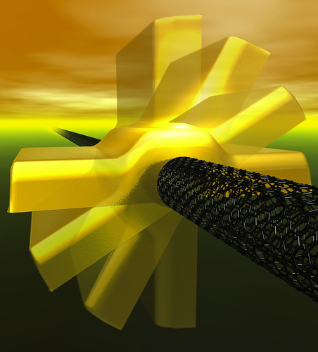
Gold nanorotor
Nanoswitch

Such nano versions of macroscopic machines are in part inspired by the visionary physicist Richard Feynman 50 years ago.  Also, fabrication and synthesis technologies has advanced enough to initialize and perpetuate the quest to miniaturize machinery in the current science and engineering disciplines. 

One of the most advanced current fabrication meths, the "top-down approach to miniturization in the semiconductor industry, is approaching the limits in scaling. For example, the band structure of silicon disappears when silicon layers are just a few atoms thick.  What about photolithography?  Well, its operational wavelengths are too limited for making nanomachines with moving parts.  

Recently, organic chemists in Rice University realized they can synthesize 3 × 4 nm nanocars in 100 mL laboratory reaction flasks–30 mg worth (that translates into 3 × 10¹⁸ nanocars–far exceeding the number of automobiles made in the history of the world.).  30 nanocars, side by side, can span the 90 nm width of a small in line in the most advanced logic chip being made today.  Tiny objects with many moving parts like nanocars have to be made differently, from the "bottom-up".  This follows more naturally in line with Darwinian evolution at the biochemical level, although we're nowhere near the sophistication of Nature's handiwork.  Consequently, molecular scientists have turned their attention to much simpler systems, where the machinery may be easier to construct and understand, perhaps serving as a base for eventual progression toward sophisticated and useful nanomachines.  

Most of the molecular machines shown above were designed and synthesized to operate in the liquid phase because of the abundant tools available to analyze products in solution.  However, useful nanomachines with mechanical functions require eventual integration into devices that interface surrounding systems (likely to operate in the solid phase).  For example, the biological nanomachine ATPase is anchored in a biological membrane in order to connect with its surroundings.  Overcoming this interface problem ranks among the most intractable of problems in nanomachine design.  

Nevertheless, there are several viable designs that (1) work in a crystalline solid, or (2) be mounted on and operated on surface, or (3) move around and operate on a surface.  
 
Machines operating in crystalline solid state
UCLA researchers have made considerable progress in the formulation, design, and preparation of crystalline molecular machines.  Examples of their work include molecular compasses and gyroscopes.  

The center component of the molecule above (red) has a magnetic moment that responds via rotation to external magnetic fields.  The plot qualitatively indicates the energy required for the rotation to occur. 

 Conventional crystalline materials have their molecular components tightly bonded and restricts their motion, which contrasts to another class of materials known as amphidynamic crystals.  These exotic crystals possess rigid lattices connected to moving parts (See pic below).   
Example of an amphidynamic crystal

Successful utilization of such crystals will lead to photonics materials whose components  stem from the bulk (not from solution or thin films), which increases the density, which leads to greater advances.  


Machines mounted and operating on a surface

Molecular machines heavily depend on positioning to be to pump, push, lift materials, or other useful work.  Examples of such machines already produced in the lab are: (see captions of following pictures)
cyclodextrin necklaces. 
J. Am. Chem. Soc. 2000, 122, 5411-5412
Molecular Shuttles,     http://www.ch.nagasaki-u.ac.jp/mol/research_e.html
Light powered molecular motor.  The absorption of sunlight by one of the two stoppers, a light-harvesting one, causes the transfer of one electron to station A, which is deactivated as far as wanting the ring to encircle it. As a consequence, the ring moves to its second port of call, station B. Station A is subsequently reactivated by the return of the transferred electron to the light-harvesting stopper, and the ring moves back to this station. Copyright © UCLA
Machines moving and operating on a surface
As if mounting nanomachines on a surface weren't hard enough, people are also trying to make them move and do stuff.  That may call for zealous usage of scanning probes such as the scanning tunneling microscope (STM).  In fact, the STM has been used to push these molecules on a surface laterally, with atomic scale precision.  Perhaps the most famous molecule used for this purpose is the molecular wheelbarrow:


(a) macroscopic wheelbarrow.  Its colors correspond to the chemical structure in (b).  (c) shows the molecule in the gas phase. 
Mechanical interactions between molecule and surface determines the molecule's motion on a variety of surfaces.  For macroscopic objects, the theory and basic rules for the design of machinery is well-known and justly exploited.  Skiing works for snow, but not for asphalt.  On water, wheels only float on their own if they're made of rubber; recommended solution, get a sailboat.  These situations don't require much brainpower to imagine, but rigorous mathematical and physical theories are necessary to explain them.  But on the atomic level, the rules are different, and therefore the normal human intuitions for working machinery do not apply.  Movement on surfaces might not follow Newtonian physics, but rather quantum mechanics.  Quantum calculations are notoriously difficult and computationally costly to obtain exact answers with the currently available tools.  For now, the development of molecular machinery depends mostly on dogged trial-and-error.  

Wednesday, December 8, 2010

Plasmonics at the bottom: Nanoshells and Invisibility Cloaks

Plasmonics may have roles to play aside from computing.  Researchers Naomi Halas and Peter Nordlander at Rice University have developed structures called nanoshells that consist of a thin layer of gold coating (usually 10 nm thick) around the entire surface of a silica particle about (100 nm in diameter).  Placing this coated particle in an electromagnetic (EM) field generates electron oscillations in the gold shell; this is due to the coupling interaction between the fields on the shell's inner and outer surfaces.  Varying the silica particle size and the gold layer thickness changes the wavelength at which the particle resonantly absorbs energy.  In short, nanoshells can be designed to selectively absorb wavelengths from the blue end of the visible spectrum (approx. 300 nm), and down to the near infrared (about 10 microns).

Surprisingly enough, nanoshells are now being considered for cancer treatment.  In 2004, Halas, working with Rice colleague Jennifer West, injected plasmonic nanoshells into the bloodstream of mice with malignant tumors and found that the particles were nontoxic.  Moreover, the nanoshells tended to embed themselves in the rodents' cancerous tissues rather than healthy ones due to higher blood circulation in the fast-growing tumors.


Additionally, human and animal tissues are transparent to radiation at certain infared wavelengths.  When near-infrared laser light is aimed at the tumors through the mice's skin, the resonant absorption of energy in the embedded nanoshells raised the temperature of the cancerous tissues from 37 ºC to 45 ºC.

This photothermal heating killed the cancer cells while leaving the surrounding healthy issue intact.  In the mice treated with nanoshells, the tumors virtually disappeared within 10 days; in the control groups, the tumors grew unabated.  As of 2009, practitioners are seeking FDA approval for clinical trials of nanoshell therapy in patients with head and neck cancer.

Plasmonics may also revolutionize the lighting industry by making LEDs bright enough to compete with incandescent bulbs.  In the early '80s, researchers found that the plasmonic enhancement of the electric field at the metal-insulator boundary could make certain dyes more luminescent if placed near the metal's surface.  This kind of plasmonic enhancement can also raise the radiation rate of quantum dots and quantum wells (tiny semiconductor structures that absorb and emit light), which improves the efficiency and brightness of solid-state LEDs.  A recent collaboration between Caltech and Nichia Corporation in Japan demonstrated that coating the surface of a gallium nitride LED with dense arrays of plasmonic nanoparticles (made of gold, silver, or aluminum) could intensify the emitted light 14-fold. 

Additionally, plasmonic nanoparticles may one day lead to LEDs made of silicon.  Silicon-based LEDs would be much cheaper than conventional LEDs composed of gallium nitride or gallium arsenide, but such devices currently emit too little light.  Research has shown that coupling silver or gold plasmonic nanostructures to silicon-dot arrays could boost their photon intensity by 10 times.  Moreover, the frequency of the enhanced emissions can be tuned by adjusting the geometries of the nanoparticles.  Simulations have indicated that careful tuning of the plasmonic resonance frequency combined with precise control of the separation between the metallic particles and the semiconductor materials may allow emission rates to rise more than 100-fold, allowing silicon LEDs to shine just as brightly as traditional devices.

Then there's the plasmonic analogue to a laser.  Mark Stockman of Georgia State University and David Bergman of Tel Aviv University theorized a new device called a SPASER (surface plasmon amplification of stimulated emission of radiation).  They have suggested fabrication methods via semiconductor quantum dots and metal particles.  The radiative energy from the quantum dots would be transformed into plasmons, which would then be amplified in a plasmonic resonator.  The plasmons generated by a SPASER  would be much more tightly localized than a conventional laser beam; this would allow the device to operate at very low power and selectively excite very small objects.  The result: SPASERs may further sensitize spectroscopy to more phenomena and to more sensitive hazardous material-detectors for minute amounts of chemicals or viruses.

Speaking of excitement, plasmonics are a potential candidate for the proverbial invisibility cloak of Hollywood films.  What is taught again and again in freshman physics is the refractive index, which is the ratio of the speed of light in a vacuum to the speed of light in the material.  If the refractive index is made equal to that of air, the object is rendered nearly invisible.  For plasmonic materials, this could be done with two things:
1) Use radiation that is close to the resonant frequency of the structure; it would neither bend nor reflect light.  The light is absorbed, never to bounce back to the observer's eye.
2) Laminate the structure with a material that produces optical gain (amplifying the transmitted signal just as the resonator in a SPASER would); the resulting higher intensity would offset the absorption losses.  The structure is thus rendered invisible, at least to radiation in a selected range of frequencies.

In theory, plasmonic materials could render objects invisible.  In one proposal, the cloaking device would be a thick shell constructed of metamaterials, which exhibit unusual optical properties.  This shell could bend radiation around its central cavity, where a spaceship could be hidden.  A space telescope pointed at the shell would see only the galaxy behind it. 
Now, it's one thing to render an object invisible for a set frequency, but it's quite another to hide it for the entire visible spectrum.  Some physicists say it is possible.  John B. Pendry of Imperial College London and colleagues showed that a shell of metamaterials might, in theory, reroute the electromagnetic waves traveling through it, diverting them around a spherical shell, as seen in the figure above.

Invisibility cloaks may never see the light of day (ha!), but such ideas highlight the wealth of optical properties that inspire scientists working in plasmonics.  By investigating the sophisticated coupling between electrons unbounded to atoms, and electromagnetic waves, researchers have identified new possibilities for transmitting data in our microchips, illuminating our homes, and fighting cancer.  Indeed, there's still a lot of 'room' to explore in plasmonics.

Tuesday, October 12, 2010

Boron Nitride nanotubes

I wrote about CNTs in my last post; figured it was inevitable since they get so much press.  I've been binging on Skeptics Guide to the Universe recently.  They're a weekly podcast that covers pseudoscience and various shenanigans in the world of nonsense.  Each podcast concludes with a segment known as "Science, or, Fiction", in which the SGU members guess which of the three science news stories is fiction (I should use this when I'm the tabletopics master in a Toastmasters meeting).  One podcast from earlier this year had a S or F story about boron nitride nanotubes, which I've never heard before.  I correctly guessed this is science, since I haven't yet heard a materials science article of their selection that turned out to be fiction. 


So, what the heck are boron nitride nanotubes? Well, to start, boron nitride (BN) is a binary chemical compound consisting of equal proportions of boron and nitrogen. It's the white material used in clown makeup and face powder.   It's isoelectronic (shares the number of electrons) with carbon, and can morph into similar physical structures: graphene-like, and diamond-like.  The latter  is the only material nearly as hard as diamond.  It remains a solid at temperatures up to 1000ºC for air, and up to 1800ºC in an inert gas atmosphere.  That's twice as high for carbon nanotubes. 

If you look for carbon on the periodic table, you may see boron is on its left, and nitrogen is on its right.  Carbon has four electrons in its valence shell, which means another four is needed to satisfy the octet rule.  Thus, boron has three valence electrons, and nitrogen has five.  Combining these two atoms satisfies the octet rule.  By extension, BN can form a graphene (1 atomic layer of graphite) lattice.  But what makes BN different from its carbon analogues is its wide band gap of approx. 5.5 eV, making a wide-gap semiconductor (effectively an insulator). 

The high bandgap for BN nanotubes (BNNT) is a factor behind their high thermal and chemical stability.  They also have excellent mechanical properties and high thermal conductivity, much like carbon nanotubes. 

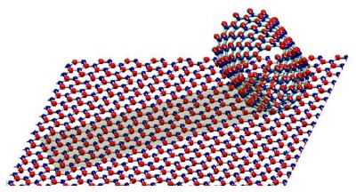
Structural models of a BN monoatomic sheet and a single-shelled BN nanotube. Alternating B and N atoms are shown in blue and red.


Boron nitrides are now being used in a rather ancient technique, the spinning of textiles into yarns.  They've already done this with CNTs as demonstrated in this video here:


Until recently, high-qualtiy BNNTs could be synthesized only up to a micron ( 1 µm) long. Longer nanotubes were riddled with crystalline defects. A team of materials scientists from four institutions
(The paper is found here) spun a ~1 mm thick yarn that looks like cotton:
This yarn is 3 cm long.  "They're big and fluffy, textile-like" said Kevin Jordan, a staff electrical engineer at Jefferson Lab.  "This means you use commercial textile manufacturing and handling techniques to blend them into things like body armor and solar cells and other applications."

How'd they spin this stuff?  By using a laser aimed at a cake of boron inside a chamber filled with nitrogen gas.  This forms a plume of boron gas that shoots upward.  They then insert a cooled metal wire into the gas, causing the gas to condense into liquid droplets.  The droplets combine with nitrogen to self-assemble into BNNTs.  It's a violent reaction that yields the long nanotubes in milliseconds. 

Mass-production of cheap BNNTs may lead to lighter, faster car frames, affordable space vehicles,  and ultralightweight armor; all promised by CNTs, but with the implication that BNNTs are simply easier to make en masse.  What separates CNTs from BNNTs in terms of utility comes down to electrical properties.  The geometry of CNTs drastically changes their conductivity. whereas BNNTs experience very little conductivity alternations with respect to geometry.  In addition, thanks to their chemical inertness, BNNTs promise "pinpoint precision to attack cancer cells by sticking to tumors, absorbing neutrons from a targeted beam, and generating local alpha radiation to kill cancer cells." (See ScienceNOW )

Wednesday, August 11, 2010

LSA experimental setup and conduction.


They used bare silicon wafers as the starting substrate. The wafers were processed through the laser anneal tool prior to inspection. Firstly, one wafer was wafer at six different temperatures at and around the process center line T°C (T-75°, T-50°, T-25°, T, T+25°, and T+50°); this minimized the effects of incoming wafer qualty on the final surface morphology. 
Wafer Schematics

Fig. 2 shows the anneal splits above. Subsequent LSA experiments utilized one wafer with one or two process conditions to verify whether this characterization is reproducibile, and for further understanding of the variations in the annealing process.

They measured the samples via KLA-Tencor’s Surfscan SP2 unpatterned wafer inspection
system. The scans were done under normal (perpendicular) incidence in high-throughput mode–the optimal scan condition for slip line detection and other shallow defects because of their defect scattering characteristics. Also, they obtained surface morphology information from the haze scattering detected on the SP2 by analyzing the so-called SURFimage (don't know what this). The SURFimage haze maps provided local surface information at pixel-level resolution and sub-nm vertical resolution. The resulting data is presented in 192-bit greyscale for clear visualization of surface variation. Each anneal zone had its haze data obtained through a newly developed capability (developed in-house) that enables local data extraction, analysis, and defect binning of local surface scattering signals using user-defined parameters. From this analysis, they correlated the results to LSA process conditions. Lastly, the authors conducted further corroboration by Scanning electron microscope.